User Guide/Workspace/Detail/Views/Signal View/Edit Sequence Signal: Difference between revisions
No edit summary |
|||
| (One intermediate revision by the same user not shown) | |||
| Line 1: | Line 1: | ||
{{DISPLAYTITLE:{{SUBPAGENAME}}}} | {{DISPLAYTITLE:{{SUBPAGENAME}}}} | ||
{{UG_Project}} | |||
This dialog is used to create or change [[User_Guide/Workspace/Detail/Detail_View/Signal_View|sequence]] signals. | This dialog is used to create or change [[User_Guide/Workspace/Detail/Detail_View/Signal_View|sequence]] signals. | ||
Latest revision as of 10:40, 14 December 2015
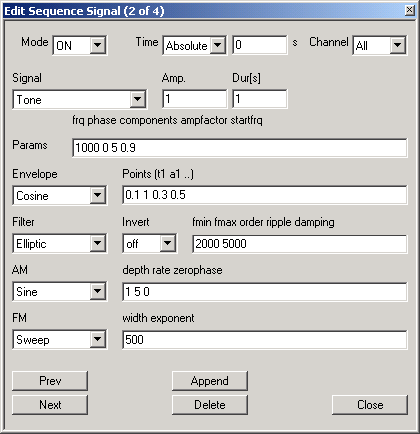
This dialog is used to create or change sequence signals.
- This section describes the controls and functions of the edit dialog. For details about the different sequence features (signal types and parameters, envelope functions, filters, modulations) read the description of the command
SET WAVE. - The Workspace uses this dialog to edit the signal definitions of sequences.
- For script programmers: The edit dialog is implemented by the class
BSeq. This class implements most sequence features. If you want to use special features like table-lookup generation/modulation or speech-synthesis you have to use the wave-item instead of this class (or to derive a special sequence class from BSeq).
Mode
Enable / disable signal generation. If disabled, the signal is not generated and placed in the sequence. Note: If a signal is disabled and relative signal positioning is used, the placement of signals in the sequence can be changed!
Time
Sets the begin time of the signal. The begin time is defined by an origin (or base) and an offset value. If the origin is set to Absolute, the time value is an offset to the beginning of the sequence (= 0s) and must be positive. If the origin is set to Begin/End the time value is an offset to the begin/end of the previous signal in the same channel and can be positive or negative.
Channel
Selects the sequence channel where the signal should be placed. A signal can be assigned to one selected channel or to all channels of the sequence.
Signal
Selects the type of signal to be generated and placed in the sequence.
| Signal | description |
| Pause | no signal |
| Segment | segment of a soundfile |
| Value | constant value |
| Noise | white noise (linear distributed) |
| Rectangle | rectangle function |
| Triangle | triangle function |
| Tone | sine tone or harmonic tone |
Amp.
Linear signal amplitude or amplification factor (for segments).
Dur(s)
Signal duration in seconds. This value is not necessary for segments because the duration is defined by the segment length.
Params
Contains the signal parameters separated by blanks. The meaning of the parameters depends on the signal type. The text above the input field shows the parameter names. A detailed description of parameters is contained in the documentation of the command: "SET sequencewaveitem SIGNAL ...".
Envelope, Points (t1 a1 ...)
Selects the type of waveform envelope and the positions of the envelope cue-points. The type can be set to none (no envelope), Linear (linear functions) or Cosine (half cosine wave). The list of cue-points specified in the field Points defines the time (t) and the amplitude (a) values of the envelope's cue-points. The time values are specified in seconds and can be positive (offset to signal begin) or negative (offset to signal end).
Filter, Invert, fmin fmax order ripple damping
An optional IIR filter can be applied to each signal. The filter algorithm is selected by the field Filter (none, Elliptic, Butterworth, Chebychew). The filter parameters are the passband frequency interval (fmin, fmax), the filter order (must be greater than 1), the passband ripple (in dB, greater than 0) and the stopband damping (in dB, greater than 0). The option Invert can be used to invert the filter spectrum (e.g. to create a bandstop or notch).
AM
Selects the type of amplitude modulation to be applied to the signal. The available types are none, Sine, Rectangle and Triangle. For the type Sine the parameters depth (a value between 0 and 1, 1 is 100% modulation), rate (the modulation frequency in Hz) and the starting phase zerophase (0 = sine, 0.5*pi = cosine) can be specified. For the Rectangle and Triangle functions the parameter dutycycle instead of zerophase is used. This parameter defines the ratio between the positive and negative part of the rectangle or the ratio between the rising and falling edge of a triangle.
FM
Selects the type of frequency modulation to be applied to the signal. Frequency modulation can only be applied to harmonic generators. The available types are none, Sine, Rectangle, Triangle and Sweep. For the types Sine, Rectangle and Triangle the same parameters as for AM are supported. For the type Sweep the parameters width (distance between frequency at beginning and end of signal in Hz, can be a positive value (raising) or a negative value (falling)) and exponent (a value greater than 0: 1 -> linear sweep, <1 -> concave sweep, >1 -> convex sweep).
Prev, Next
Go to the definition of the previous/next signal.
Append
Append the signal definition as last signal to the list of defined signals.
Delete
Delete the currently edited signal.
Close
Save changes and close.
